Short-circuit indicators for overhead lines of voltage classes from 6 to 110 kV are designed for prompt detection and localization of an overhead line section where an interphase short circuit or a single-phase ground fault has occurred. Indicators allow to reduce the time of searching for damages and elimination of faults on the line due to network sectioning and, as a result, a shorter section for bypassing. As a result, losses of energy companies associated with undersupply of electricity and fines from consumers are significantly reduced.
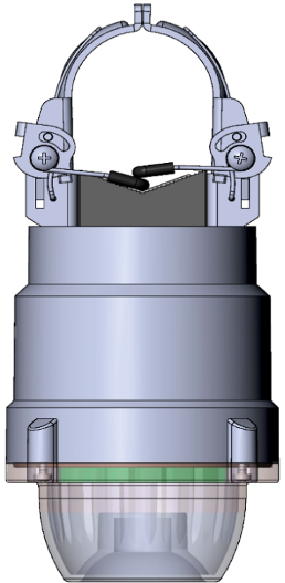
Short–circuit indicator
The principle of operation of the equipment
Each of the devices installed (depending on the modification) on a support or a phase wire of an overhead line measures the current instantaneous value of currents and voltages in the phase wires, calculates the value of the amplitudes of currents and voltages and compares the obtained values with the setting values in a constant mode. Current values are measured by inductive sensors made in the form of ferromagnetic cores; voltage values are measured by capacitive sensors. Both sensors are non-contact and are located in the hermetic case of the device. The received data is processed by the built-in controller, the control algorithm allows you to select from the data stream exactly those ones that signal an emergency. When the preset settings are exceeded, the devices start indicating an emergency situation corresponding to the type of accident (interphase short circuit or single-phase earth fault) using super-bright LEDs or blinkers with a reflective coating, and also to record the alarm parameters.
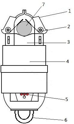
1 – metal petals of the magnetic circuit;
2 – pressure rubberized springs for fixing the indicator on the wire;
3 – a box for a wire;
4 – indicator case;
5 – LEDs;
6 – ring for setting the indicator (manually or using a rod);
7 – wire on which the indicator is installed.
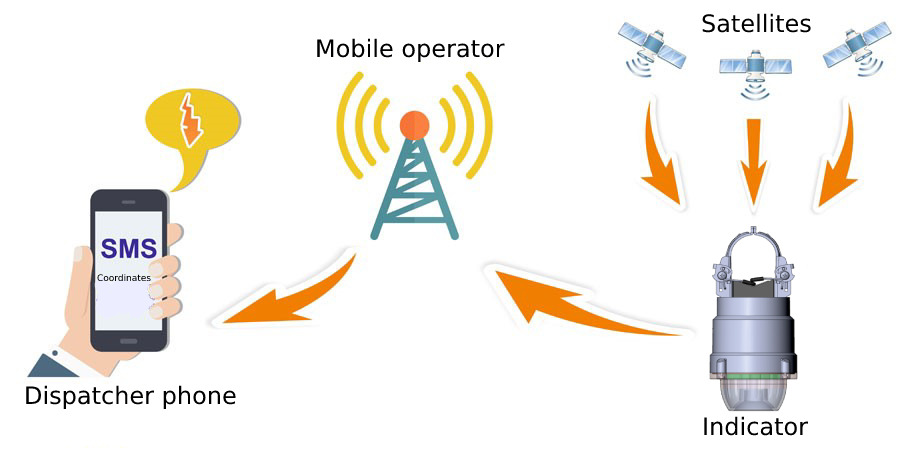
Information from the device can be perceived visually (super-bright LEDs are visible 100 m before the support on which the indicators are installed on a sunny day), read using a portable remote control via a short-range radio channel. There is an additional possibility to organize the display of information about the accident and its parameters on the screen of the dispatcher console (including integrating information into the SCADA system), which will allow the dispatcher to send an emergency team directly to the emergency site. Devices can be configured without removing them from the overhead line support using a remote control, for example, depending on the settings, the alarm indication can stop when voltage is applied to the overhead line, after a certain interval (set from the remote control) or manually using the remote control.
Scheme of data transfer in case of short circuit from the indicator to the dispatcher’s phone
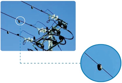
Sets of indicators are installed at a certain interval along the overhead line (approximately 2 km), as well as at the beginning of each branch line from the overhead line. The search for the accident site is carried out by sequential inspection of the status of the indicators, starting from the substation supplying the overhead line. In the direction of movement from the substation, all indicators located before the accident site will indicate the accident with light-emitting diodes or blinkers with a reflective coating, and the indicators located after the accident site will be “silent”. Therefore, it becomes possible to quickly find the area where the accident occurred. If an accident occurred on a branch line from the overhead line, then the indicators installed at the beginning of the corresponding branch line will point to it – this branch line can be turned off and examined without disturbing the operability of the rest of the line.
Short-circuit indicator installed on a 10 kV overhead line
A number of modifications of short circuit indicators are produced, they differ in methods of measuring the parameters of overhead lines, sensitivity to minimum values of short circuit currents, methods of powering devices, methods of indication and communication. To indicate and transmit data about an accident, devices can use blinkers with a reflective coating, super-bright LEDs, a short-range radio channel, data transmission over GSM networks, wired communication (using IEC-60870-5-104 protocols), relay outputs. Various modifications of devices will allow you to choose the optimal model for solving your problem based on such parameters as: power transmission line parameters (overhead line length, existence and number of taps, operating current, typical currents in case of phase-to-phase and single-phase faults), existence of stable mobile communication in the region where your power transmission line is located, need to integrate data into a top-level system, etc.
Product advantages
Main advantages of Short-circuit Indicators
Unlike products of similar purpose of different developers offered on the market, including Russian brands, indicators were developed taking into account the features of Russian distribution networks. This specificity lies in the fact that the vast majority of overhead transmission lines in Russia with voltage classes of 6-10-15-20-35 kV have an isolated neutral, and, as a result, significantly lower single-phase ground fault currents than in networks with a grounded neutral common in foreign countries. At the same time, it is single-phase ground faults that cause the greatest problems to operating organizations due to the high frequency of occurrence and the increased complexity of detecting such emergencies. Short-circuit indicators operation thresholds allow devices to confidently determine the single-phase ground faults on overhead lines, without taking any measures to increase the single-phase ground faults current, which require the installation of additional equipment at the substation, changing the settings of existing equipment, etc.
The devices are designed and manufactured in Russia. STC Practic-Novator has exclusive rights to distribution of products in Russia and the CIS countries.